Antenna Pattern Editor 3.0
Tool to View, Generate, Edit and Convert Antenna Pattern Files
User Manual


From the Developers
We made every effort to create a user-friendly and intuitive application. However, we recommend that you spend some time reading this User Manual to get the most out of the Antenna Pattern Editor.
Features
Antenna Pattern Editor is a versatile tool that allows you to view, create, edit, and convert antenna pattern files. The main idea behind the program is to provide users with the ability to quickly create an antenna pattern file using various methods.
An antenna pattern file is a simple text or XML file that describes the main characteristics of an antenna - radiation patterns, gain, frequency range, name, manufacturer, and other data. These files are used in various radio planning tools including our RadioPlanner, Indoor RadioPlanner, MLinkPlanner and EMF Planner.
Due to the large number of antenna pattern file formats, it often happens that an antenna pattern file in the exact format you need is not available. In this case, using Antenna Pattern Editor, you can easily convert the file to the format you need.
Sometimes the antenna information is just a picture of the antenna pattern. In such cases, using Antenna Pattern Editor, you can prepare the necessary file in just a few minutes. Thanks to its simple graphical interface and cubic spline interpolation algorithm, you can get the desired file by pointing out only a few characteristic points on the downloaded image. You can use images in any raster format - png, jpg, bmp, tiff.
With Antenna Pattern Editor, you can view, compare, edit, transform and normalize antenna patterns as well as perform a number of other functions described below.
Features:
- View 2D/3D antenna patterns in linear and logarithmic scales
- View text information from antenna pattern file
- Create/edit the antenna pattern in the table form with advanced copy and paste capabilities
- Create an antenna pattern from the picture (digitizing)
- Perform various transformations of antenna pattern (rotation, mirroring, normalize, etc.)
- Create of antenna patterns on various ITU-R reference models
- Antenna pattern report in Word, Excel, and PDF
- Export antenna patterns to various formats
- Calculation of the width of the main lobe in the horizontal and vertical plane, as well as the electrical antenna tilt
- Create an antenna pattern envelope file from a set of antenna patterns
Antenna Pattern Editor supports most antenna pattern file formats. Both simple formats with two patterns in azimuth and elevation planes (e.g., MSI Planet, Radio Mobile V3, Ekahau *.json antenna pattern) and more complex formats with antenna patterns in different polarizations and “slice” formats (NSMA, TIA/EIA-804-B, EDX) are supported. Full 3D formats ETS-Lindgren and Satimo are also supported.
Supported antenna pattern file formats:
- MSI Planet (*.msi, *.pla, *.pln, *.ptn, *.txt, *.ant)
- Radio Mobile V3 (*.ant)
- NSMA WG16.99.050 (*.adf *.dat *.nsma *.nsm *.txt)
- TIA/EIA-804-B (*.adf)
- Atoll (*.txt)
- Asset (*.xml)
- Mentum Planet (*.pafx)
- EDX (*.pat)
- Ekahau (*.json)
- AntPat (*.ana)
- CelPlan (*.txt)
- RadioSoft ComStudy (*.pt2)
- V-Soft (*.pat, *.vep)
- 3D formats: ETS-Lindgren, Satimo (*.csv), Systems Tool Kit (STK), (*.txt)
Samples of all these files can be found in the folder with the installation file.
Installation and Activation
Antenna Pattern Editor is compatible with x64 and ARM processors on Windows 10/11. The minimum computer configuration required is a Core i3 CPU, 4 GB RAM, 200 GB HDD, a video card, and a monitor with support for 1366x768 resolution.
To install the program, run the Setup_AntennaPatternEditor.exe file. Select your language and click Install to launch the installation process. Click Next. To continue the installation process, read and accept the License Agreement by activating the checkbox “I accept the terms in the License Agreement” and clicking Next.
After installing Antenna Pattern Editor, you will see a new entry in the Start menu and a shortcut on the desktop.
During the 30-day trial period, you can try most of the program's features, except for export. To use all the features in the software, you need to purchase a license and activate the software.
To purchase Antenna Pattern Editor, click on Help - Purchase. This will open the purchase page in your browser. After making a purchase, you will immediately receive an activation ID code via email. Then click Help - Enter your Activation ID code, enter your code and click ACTIVATE.
Software Update
We periodically release free updates that improve the functionality and stability of the software.
Antenna Pattern Editor supports both manual and automatic update checks. The program will check for available updates each time it starts. To check for updates manually, click Help - Check for Updates. If an update is available, a window will open displaying the current and available versions. Download the update from the provided link and install it manually (make sure to close Antenna Pattern Editor before installing the update).
How to Work with the Antenna Pattern Editor

The general principle of Antenna Pattern Editor’s operation can be understood from the block diagram above. The program has several blocks, each with its own function:
Files: Here you can view antenna files, prepare antenna specification in Microsoft Word, select an antenna pattern for direct export to other formats or for further editing. Here you can also compare the patterns of two antennas and view the antenna model in 3D.
Editor: Here you create/edit a new antenna pattern in tabular form and perform transformations, normalization and other processing of the antenna pattern. The Editor also allows you to digitize the antenna pattern represented as an image.
Here you can also create an antenna pattern based on ITU-R reference models and obtain an antenna pattern envelope from a set of individual antenna patterns. This is often required to determine the worst-case radiation situation in terms of EMF exposure.
Export: Here you can export the antenna pattern to various formats. The antenna pattern for export can be obtained directly from the Files viewer or from the Editor.
User Interface
The user interface of Antenna Pattern Editor uses a Tree View interface (multi-level tree) as its main user menu. The controls for this interface are located on the left side of the main panel. When you select a menu item, the corresponding panel opens on the right.
View and Select Antenna Pattern File
The Antenna Pattern Editor allows you to view antenna patterns and other information from antenna pattern files. You can open a file or folder in the standard way, or simply drag the desired file or folder into the Antenna Pattern Editor window. Navigation is performed using the built-in directory tree. File names with extensions commonly used for antenna patterns are displayed in normal font, other file names are displayed in italics.
Toolbar:
Open antenna pattern file
Copy selected antenna patterns to Editor
View antenna datasheet report in Microsoft Word
Export selected patterns
For simple antenna file formats consisting of only two antenna patterns in the H and V planes (MSI, Radiomobile, etc.), the antenna pattern image will immediately appear on the display. For more complex file formats containing multiple antenna patterns, you will be able to select the desired pattern to view.
All text information about the antenna pattern parameters contained in the file will appear next to the antenna pattern image.

View Antenna Pattern Files
You can use the tools located to the right of the antenna pattern to change the display of the antenna pattern - in relative units (E/Emax) or dB. The scale is set automatically, but for dB, you can also set the scale manually by clicking on Manual and moving the slider. If the antenna pattern is not normalized, a corresponding mark will appear above it.
Using the controls above the antenna pattern, you can select its representation (in polar or Cartesian coordinate system) as well as the antenna pattern orientation (up or right). This allows you to customize the display of the antenna pattern to your preferences.

Antenna Pattern in Cartesian Coordinate System

Viewing an antenna file in PAFX format

Viewing an antenna file in EDX format with slices
The width of the main lobe is displayed at a level of 3 dB (E/Emax=0.7) on both the horizontal and vertical antenna patterns. The main lobe azimuth and vertical tilt are also displayed. These values are calculated from the information in the antenna pattern file.
To use the selected antenna pattern for further editing, click the "Copy selected patterns to editor" button, after which the editor will open with its copy. If you select several antenna patterns, all of them will be copied to the Editor.
To directly (without editing) convert the selected antenna pattern or several antenna patterns to another format, click the "Export selected patterns" button and select the format you need. After that, a copy of the antenna patterns will be transferred to the corresponding export menu. Please note that copying several antenna patterns is only possible when exporting to formats that allow saving several patterns in one file (Atoll, Asset, PAFX).
Comparison of two antenna patterns
Antenna Pattern Editor allows you to compare the patterns of two antennas. To do this, you can select the first pattern and click on the “Add antenna pattern to comparison” button. The name of the antenna will be displayed below the diagram in green, and the antenna pattern will be frozen in the diagram with a green outline. Now you can select the second antenna and visually compare the two antenna patterns. This feature allows you to easily compare and evaluate the differences between two antenna patterns.

Comparison of two antenna patterns
Add antenna pattern to compare
Remove antenna pattern from comparison
Antenna Datasheet
The Antenna Pattern Editor provides an antenna datasheet report that opens directly in Microsoft Word. Select one or more antenna patterns and click "View antenna datasheet report in Microsoft Word". You must have Microsoft Word installed on your computer to obtain this report.

Multi-page Report in Word
3D Visualization of 2D Antenna Patterns
Antenna Pattern Editor can perform 3D visualization of regular 2D antenna patterns presented in horizontal and vertical planes, as well as slice-type antenna patterns. The conversion of 2D antenna pattern into 3D is performed using the CrossWeighted conversion algorithm.
To view the antenna pattern in 3D, you can click on the 3D button, which is located in the upper right corner. The 3D model of the selected antenna will open in a separate window. The 3D visualization controls are at the top. Rotation of a 3D visualization is most conveniently performed using the ViewCube in the upper right corner. The ViewCube is a cube-shaped widget placed in an upright corner of the window. When used as an orientation controller, the ViewCube can be dragged, or the faces, edges, or corners can be clicked on, to easily orient the scene to the corresponding view. When acting as an orientation indicator, the ViewCube turns to reflect the current view direction as the user re-orients the scene using other tools.

3D visualization of 2D antenna pattern
Working with Original 3D Antenna Patterns
View original antenna patterns in 3D format
The Antenna Pattern Editor allows you to view real 3D antenna patterns in the following formats:
- Tabulated echo chamber data (ETS-Lindgren, Satimo, and similar)
- Systems Tool Kit (STK) format
The Systems Tool Kit (STK) format is directly supported.
To view an echo chamber file containing actual measured antenna radiation patterns in 3D, it must first be converted into a simple text table. Such a file typically contains antenna radiation pattern measurements in spherical coordinates for theta and phi angles in various frequency ranges. From this file, you can easily create a 3D file compatible with Antenna Editor using any spreadsheet program.

Original 3D antenna pattern
Paste 3D data from clipboard
Antenna maximum radiation vector (Z or X)
In order for a 3D antenna file to be read by the Antenna Pattern Editor, it must be in the following text format (*.csv, *.txt) spreadsheet:
1. The spreadsheet must contain Theta angle values in the range of 0 to 180 degrees and Phi angle values in the range of 0 to 359 degrees in increments of 1 degree or more. Phi and Theta angles can be arranged in either rows or columns.
2. If the Phi values in the table are in columns and the Theta values are in rows, then the first cell of the table should contain the text ThetaPhi; if the Phi values are in rows and the Theta values are in columns, then the first cell of the table should contain the text PhiTheta.
3. The remaining cells of the spreadsheet, except for the first, must contain the values of the antenna pattern in dBi in normalized or absolute values.
4. The cell separator can be a comma, semicolon or TAB.
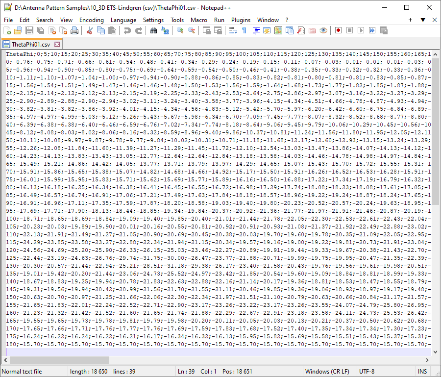
Sample 3D Antenna Pattern in Text Table Format
Paste 3D data from clipboard
Using the "Paste from Clipboard" tool, you can paste 3D antenna pattern data directly into the Antenna Editor table by simply copying it from any table in Excel or Word.
Examples of tables:
Theta by rows, Phi by columns:

Phi by rows, Theta by columns:

Converting an Antenna Pattern from 3D to 2D
RF planning or EMF exposure calculation software most often uses a two-dimensional antenna pattern, which is an antenna with radiation patterns in both the horizontal and vertical planes.
The Antenna Pattern Editor allows you to transform 3D antenna slice selected by the Phi angle into 2D with the formation of corresponding antenna patterns in the horizontal and vertical planes. The resulting 2D antenna patterns are displayed in the viewing area and can be sent directly to the export form or copied to the Editor for further editing as 2D antenna patterns.
There are two options for converting the antenna pattern from 3D to 2D. The choice of one or another option for conversion is determined by how the antenna was positioned relative to the axes during measurements on the stand.
The antenna can be positioned with maximum directivity either along the X axis (usually for omni antennas) or along the Z axis (usually for directional antennas), see the explanatory figure below.

Converting a 2D to 3D radiation patter
The Antenna Pattern Editor allows you to convert 2D antenna patterns into 3D ones for further saving in 3D format (currently in STK format; see the "Export to STK" section). In the Viewer or Editor window, use the "Export to 3D" tool and select the conversion options from the menu that appears.

Convert antenna pattern to 3D format
If during measurements on the stand the antenna was positioned with maximum radiation along the Z axis, then in the toolbar you need to select .
If during measurements on the stand the antenna was positioned with maximum radiation along the X axis, then in the toolbar you need to select . For this case, to generate an antenna pattern in the horizontal plane, you can take into account the projection of the antenna pattern onto the XY plane.
Editor
As mentioned above, in the Editor section you can do the following:
- Create new/Table edit/Transform antenna pattern
- Create antenna pattern with Paste from Clipboard Wizard
- Create an antenna pattern from an image (digitize)
- Create of antenna patterns based on ITU-R reference models
- Create antenna pattern envelope for selected antenna patterns
You can manually fill in and edit the table, and there are also advanced options for copying and pasting table cells using the Paste from Clipboard Wizard from spreadsheets, text files, and even antenna patterns from FM and TV queries from the FCC website www.fcc.gov. This makes it easy to work with antenna patterns and make any necessary changes or transformations.
When an antenna pattern is placed in the editor, regardless of its previous format, the antenna pattern values are converted to a universal form in which dB values can be either positive or negative, and the angles will always be in the range of 0 to 360 degrees.

Editor
Main Toolbar
Add a new antenna pattern to the list
Load antenna patterns from *.APX file
Save antenna patterns to *.APX file
Clear antenna pattern list
Create envelope antenna pattern for selected antenna patterns
Create envelope antenna pattern for selected antenna patterns
Paste from Clipboard Wizard
Export selected antenna patterns
Undo
Redo
dB
Values Units in the Editor:
- dB
- Relative (E/Emax)
- dB + Relative (E/Emax)
Transformation of Antenna Pattern
You can use the tools in the Transformation menu of Antenna Pattern Editor to perform various transformations of the antenna pattern in the horizontal and vertical planes. This allows you to easily manipulate and modify the antenna pattern to meet your needs.
Toolbar for horizontal and vertical planes:
- Fill the table with azimuths/elevations at a given interval
- Copy selected cells to the clipboard
- Paste data from clipboard
- Copy all cells to the clipboard
- Replace all cells with data from the clipboard
- Make all dB values negative. This conversion is required when copy-pasting into a table of values from a text file of antenna patterns in MSI format
- Normalize or set any absolute maximum values of the antenna pattern
- Simplify antenna pattern by using Douglas-Peucker algorithm
- Interpolate in 1 degree step
- Rotate the antenna pattern clockwise 1 degree
- Rotate the antenna pattern counterclockwise 1 degree
- Copy the antenna pattern from top to bottom
- Copy the antenna pattern from bottom to top
- Rotate the antenna pattern clockwise 90 degree
- Vertical mirroring of the antenna pattern
- Tilt both sides of the antenna pattern 1 degree down
- Rotate both sides of the antenna pattern 1 degree up
- Copy the right side of the antenna pattern to the left
- Copy the left side of the antenna pattern to the right
- Swap antenna pattern panels
Manual Entry and Editing of Antenna Patterns
When manually entering and editing an antenna pattern in the Editor, you can simply enter the angle values and the corresponding antenna pattern values in logarithmic or relative units (the units are set in Toolbar). You only need to enter one of the values, and the other will be calculated automatically. To delete rows in the table, you can select these rows in the left empty field and press Delete on your keyboard.
Any action in the editor can be undone or redone using the undo and redo tools.
Copying Antenna Pattern Data from Spreadsheets and Text Files Using the Paste from Clipboard Wizard
Paste from Clipboard Wizard is a universal tool for copying and pasting antenna patterns from any text file or spreadsheet.

Paste from Clipboard Wizard
Delimiters
Delimiters in copied text or spreadsheet between angle data and antenna pattern data in horizontal and vertical planes
Angle
The column number with angle data in the copied text, or setting angles directly.
Horizontal plane
The column number containing data on the antenna's horizontal radiation pattern or an indication that this data is not present in the copied text.
Vertical plane
The column number containing data on the antenna's vertical radiation pattern or an indication that this data is not present in the copied text.
Units
Units (dB or relative) of imported antenna patterns.
Change sign
Change the sign of units during import
Angular increment direction
Direction of angular increment when there is no column with angles in the imported data
First point angle
Angle of the first point when there is no angle column in the imported data
Point spacing
Point spacing when there is no column with angles in the imported data
Copy the antenna pattern data from a text file or spreadsheet and run Paste from Clipboard Wizard. Specify the symbols that are used in your file to delimit the values of different columns (for spreadsheets, this is TAB), and also select the column number in the copied data for the angle values and the antenna pattern in the horizontal and vertical planes. If the data you copied does not have a column with angles, you can specify the angles directly with the desired spacing. If there is no antenna pattern for a particular plane in the data you copied, you need to select "Not Set" for that plane. After setting up the import, click "Paste." If you imported one plane, repeat the settings for the second plane and click "Paste."

Copy antenna pattern from a text file

Copy H-plane antenna pattern from an Excel file
We have prepared a video on working with Antenna Pattern Editor, which shows examples of importing antenna pattern data using Paste from Clipboard Wizard from various text file and spreadsheet options.
Copy Antenna Pattern from FCC Website
In Paste from Clipboard Wizard, you can also copy antenna patterns from standard FM and TV query results directly from the FCC website. By using these queries, you can find the antenna parameters of FM and TV broadcasting stations in the FM, VHF, and UHF bands. Queries are made from addresses https://www.fcc.gov/media/television/tv-query and https://www.fcc.gov/media/radio/fm-query. Queries can be made by various parameters such as call sign, state, city, etc. Simply copy the data lines from the website for the antenna azimuth pattern and click "Paste" in the appropriate section of the Paste from Clipboard Wizard.

Copy antenna pattern from FCC website
Digitizing of the Antenna Pattern Picture
In cases where the antenna pattern is presented as an image, you can prepare an antenna pattern file by digitizing this image. To do this, you can upload a file with a picture of a horizontal antenna pattern, mark several characteristic points on it, mark the center of the polar coordinate system, and one or more levels in dB of the antenna pattern. Then, you can perform the same operations with the vertical antenna pattern, fill in several fields with the antenna parameters, and save the antenna pattern in the desired format.

Digitization of antenna pattern in the H-plane
Toolbar:
- open antenna pattern image (* .png, * .jpg, * .bmp, * .tiff)
- point the center of the polar coordinate system on the image
- rotate 0-degree antenna pattern direction
- point the appropriate level in the image
- delete all pointed levels
- change the color of the resulting antenna pattern line
- clear the antenna pattern line
- units
- Finish digitizing the Horizontal/Vertical plane and copy it to the Editor.
dB
Here is a detailed step-by-step procedure for digitizing an antenna pattern picture using Antenna Pattern Editor:
Step 1. Go to the Digitization – Horizontal Plane. Download the image file of the antenna pattern in the horizontal plane, or paste the image from the clipboard. You can move the downloaded image by holding down the mouse wheel and dragging, and you can scale it by rotating the mouse wheel.
Step 2. Set the center of the polar coordinate system to the center of the antenna pattern. Click on the tool , and then click on the center of the downloaded image antenna pattern.
Step 3. Using the tool , specify the direction of the antenna pattern by 0 degrees (antenna manufacturers provide the antenna pattern, in which the direction of the antenna pattern at 0 degrees is sometimes indicated up, sometimes to the right).
Step 4. Using the dB - E/Emax tool, specify the units in which the antenna pattern in the image is shown - in decibels or relative units.
Step 5. Set the nodes of the polyline (it is marked in blue) on the characteristic points of the image of the antenna pattern (usually these are the maxima and minima of the antenna pattern, as well as the characteristic bends of the antenna pattern). You can move a polyline node by clicking it with your left mouse button, delete a node by clicking it with your right mouse button, and create an additional node by clicking on a polyline with your right mouse button.
Step 6. Evaluate the coincidence of the resulting antenna pattern, which is shown in red (the color can be changed using the tool ) with the original image of the antenna pattern. To make the resulting radiation pattern smooth in any of the nodes, you should enable spline interpolation in it by double-clicking the left mouse button, and the node will be highlighted in red. If necessary, add additional nodes (do not forget - nodes are added on the blue polyline with the right mouse button) until a satisfactory match with the picture is obtained.
Step 7. If the antenna image is given in decibels in the original image, then you need to specify the levels from the range -3, -10, -20, -30 or -40 dB, which are marked on the loaded image of the antenna pattern (several are better, since the scale on image antenna pattern may be non-linear). To do this, click on the desired button, and then click on the appropriate level in the image antenna pattern. If the antenna image is shown in relative units on the image, then the -3, -10, -20, -30, and -40dB levels are not required, except for the following case. Very rarely, but it happens that some manufacturers draw the antenna pattern in relative units, in which 0 is not in the center, but at a certain radius from the center. In this case, at a radius corresponding to 0, you need to specify the level of -40dB. This level will be taken as 0.
Step 8. Click on button to digitize the horizontal-plane antenna pattern. Then it will appear in the Editor menu.
Step 9. On the Vertical Plane tab, repeat steps 1-8 for the Vertical plane antenna pattern.

Digitization of antenna pattern in the V-plane
The Antenna Pattern Editor presentation video on our YouTube channel shows in detail the process of digitizing an antenna pattern.
Creating an Antenna Pattern Using a Graphical Editor
Using the digitizer, you can quickly draw an antenna pattern from a blank antenna pattern in a logarithmic or linear scale. Blank templates can be opened for the horizontal and vertical antenna pattern with the tool . Next, you must specify the values of the antenna pattern on the blank template in accordance with the step-by-step instructions outlined in the section on Digitizing the antenna image.

Drawing an Antenna Pattern Using a Blank Template
Antenna Pattern Synthesis Based on ITU-R Reference Models
Using the Create New Antenna Pattern Using Reference Models tool on the main toolbar of the Editor, you can synthesize an antenna pattern using reference models based on information about the main characteristics of antennas, such as main lobe width, side lobe level, frequency range, tilt, etc.

Antenna Pattern Synthesis by Reference Models
For sector and omnidirectional antennas, the synthesis of radiation patterns is carried out in accordance with Rec. ITU-R F.1336-5 “Reference radiation patterns of omnidirectional, sectoral and other antennas for the fixed and mobile service for use in sharing studies in the frequency range from 400 MHz to about 70 GHz”.
3 dB beamwidth in the azimuth plane (degree)
3 dB beamwidth in the azimuth plane (degree)
3 dB beamwidth in the elevation plane (degree)
3 dB beamwidth in the elevation plane (degree)
Beam tilt (degree)
Beam tilt (degree)
Pattern Type:
- Peak side-lobe
- Average side-lobe
Type of antenna pattern approximation:
- on the peaks (maximums) of the side lobes
- the average level of the side lobes
Antenna Type
- Typical antenna
- Improved side-lobe performance antenna
Antenna Type
- Typical antenna
- Improved side-lobe performance antenna
- Create a H-plane pattern
- Create a V-plane pattern
- Create an antenna pattern
For rotationally symmetrical antennas (microwave antennas and satellite earth stations antennas), the synthesis of the antenna pattern is carried out in accordance with Rec. ITU-R F.699-8 “Reference radiation patterns for fixed wireless system antennas for use in coordination studies and interference assessment in the frequency range from 100 MHz to 86 GHz”.
Frequency (MHz)
Frequency (MHz)
Antenna gain (dBi)
Antenna gain (dBi)
Antenna diameter (m)
Antenna diameter (m)
Another common antenna synthesis method that can be used in the program is synthesis using a sinusoidal function and viewing angle.
3 dB beamwidth in the azimuth plane (degree)
3 dB beamwidth in the azimuth plane (degree)
3 dB beamwidth in the elevation plane (degree)
3 dB beamwidth in the elevation plane (degree)
Beam tilt (degree)
Beam tilt (degree)
Viewing angle in the elevation plane (degree)
Viewing angle in the elevation plane (degree)
Side-lobe level (dB)
Side-lobe level (dB)
Creating an Envelope Antenna Pattern
The Generate Envelope Antenna Pattern for Selected Antenna Patterns tool in the Editor allows you to generate an Envelope Antenna Pattern from a set of individual antenna patterns. This is often required to determine the worst-case radiation situation in terms of EMF exposure.
The envelope is created based on the selected antenna patterns from the set in the Editor. Select the patterns you need in the list and click "Create Envelope Antenna Pattern for Selected Antenna Patterns" button on the Editor toolbar. The resulting envelope will be created and placed at the end of the list. The gain of each selected antenna pattern will be taken into account when calculating the envelope.

Create an Envelope Antenna Pattern
Export Antenna Pattern to Files of Various Formats
Antenna Pattern Editor allows you to export the antenna pattern to various formats. The antenna pattern(s) for export can be obtained directly from the File viewer or from the Editor.
Export file formats:
- MSI Planet
- Radio Mobile V3
- EDX Signal
- NSMA/TIA/EIA
- Ekahau (*.json)
- PAFX Planet
- Atoll
- Asset
- Systems Tool Kit (STK)
The export preparation algorithm takes into account the features of each format.
Export to MSI Planet/ Radio Mobile/ EDX Signal/ Ekahau/V-Soft format

Export Antenna Pattern to MSI file

Export Antenna Pattern to Ekahau *.json file
Export to Atoll/Asset/NSMA format
Exporting to these more complex file formats containing multiple antenna patterns is done by copying the pattern set directly from the Viewer or Editor into the appropriate export window. The information for the text fields will also be copied. The user only needs to make changes to the standard text fields (if necessary) and save the file.

Export to Atoll file format

Export to Asset file format
Export to PAFX format
The PAFX file is an archive of a structured XML file containing parameters of modern multiport antennas, including radiation patterns for all ports, frequency ranges, polarizations, and electrical tilt angles.
When directly exporting a PAFX file from the File Viewer (for example, if the user only needs to make minor changes to the file), the file structure is completely copied to the export window.
For direct export from other file formats or from the Editor, you must first prepare the antenna file structure - create ports and bands. After that, you can copy sets of antenna patterns to the corresponding bands.

Toolbar:
Export to PAFX file format
Save PAFX file
Clear antenna pattern parameters
Make the antenna pattern names as AntennaName_Port_ElectricalTilt_MesurementFrequensy. This tool is designed to create unique names for all antenna patterns to correctly save a set of XML files.
Additionally, you can create electrical tilt angle controllers within the software.
To create or edit the antenna structure, use the right mouse button. Antenna parameters can be specified in the properties panel displayed on the right. Radiation patterns for a selected frequency range are imported from Editor.


Editing antenna structure elements in PAFX format
Export to STK format
Antenna Pattern Editor 3.0 supports exporting antenna patterns to 3D STK format for Systems Tool Kit software.
Export is done by copying the antenna pattern from the Viewer or Editor into the 3D Formats export window and saving the file using the appropriate tool on the toolbar.

Export antenna pattern to STK format
Toolbar:
Save antenna pattern file to STK format
Appendix 1. Antenna pattern formats
MSI Planet Antenna Pattern File Format
Planet is a RF propagation simulation tool initially developed by MSI. Planet was a 2G radio planning tool which has set a standard in the early days of computer aided radio network design. The antenna pattern file and the format which is currently known as ".msi" format or .msi-file has become a standard.
The antenna pattern file is an ASCII Text file and the general information; horizontal data points and vertical data points are stored in one file. The left column label and the data is separated by at least one space. The horizontal data and vertical data can be separated by at least one space or a Tab character.
There must be 360 data points (0 through 359) for the Horizontal data and 360 data points (0 through 359) for the Vertical data. Zero degrees represents North for the Horizontal pattern, and Zero degrees represents the horizon for the Vertical pattern. The antenna gain unit is dBd. If the Gain is in dBi, it must be indicated after the Gain value (separated with at least one space). All gain data points are relative to maximum gain being zero. Any value below zero is assumed to be negative. Do not include the minus sign for these values.
The name of the antenna should be the first line of the file.
The name of the antenna should be the first line of the file
antenna.msi
NAME <name>
MAKE <make>
FREQUENCY <frequency>
H_WIDTH <h_width>
V_WIDTH <v_width>
FRONT_TO_BACK <front_to_back>
GAIN <gain>
TILT <tilt>
POLARIZATION <polarization>
COMMENT <comment>
HORIZONTAL 360
0 <0H>
.
.
359 <359H>
VERTICAL 360
0 <0V>
.
.
359 <359V>
Variables:
Variable Comment
NAME Name of the antenna
MAKE Name of the manufacturer
FREQUENCY Frequency in MHz
H_WIDTH Opening angle in the horizontal plane between the -3 dB points
V_WIDTH Opening angle in the vertical plane between the -3 dB points
FRONT_TO_BACK Front to back ratio in dB
GAIN Antenna gain in dBd when in dBi this must be specified
TILT Electrical tilt of the main beam in degrees
POLARIZATION Horizontal, vertical, +45 or -45
COMMENT Comment
0H..359H
Horizontal gain datapoints per horizontal angle relative to maximum gain being zero. Any value below zero is assumed to be negative. Minus sign is not used with these values
0V..359V
Horizontal gain datapoints per horizontal angle relative to maximum gain being zero. Any value below zero is assumed to be negative. Minus sign is not used with these values
Sample file:
Restrictions when exporting to the MSI file format:
If the antenna pattern in the editor contains sets of patterns for different polarization or slices, then only the set that is currently displayed will be exported.
If the antenna pattern in the editor contains a number of points other than 360, then these patterns will be converted to the format 0-360.
If the antenna pattern in the editor does not contain a full 360-degree circle, then the antenna pattern values in the missing sector will be linearly interpolated.
Radio Mobile V3 Antenna Pattern File Format
This antenna pattern file format is used in the popular free radio planning application Radio Mobile.
This format stores the antenna pattern in the horizontal plane and the pattern in the vertical plane in one file.
More information about the format can be found at the link:
http://radiomobile.pe1mew.nl/?The_program:File_formats:Antenna_.ant_format_%28V3%29
Restrictions when exporting to the Radio Mobile file format:
If the antenna pattern in the editor contains sets of patterns for different polarization or slices, then only the set that is currently displayed will be exported.
If the antenna pattern in the editor contains a number of points other than 360, then these patterns will be converted to the format 0-360.
If the antenna pattern in the editor does not contain a full 360-degree circle, then the antenna pattern values in the missing sector will be linearly interpolated.
EDX Signal Antenna Pattern File Format
This antenna pattern file format is used in EDX Signal/Signal Pro planning tools.
This format stores the antenna pattern in the horizontal plane and a set of slices in the vertical plane at given azimuths in one file.
More information about the EDX Signal format can be found at the link:
https://help.edx.com/help/directional-antenna-pattern-file
Restrictions when exporting to the EDX file format:
The antenna pattern in the horizontal plane can contain any number of points.
All slices must contain the same number of points in the range of -90 to +90 degrees.
If the antenna in the editor contains several sets of antenna patterns in different polarization, then the set that is currently displayed will be saved.
If the current format does not support slices (for example, the MSI format), then two slices will be created during saving at azimuths of 0 and 180 degrees.
NSMA and TIA/EIA-804-B Antenna Pattern File Format
In NSMA antenna pattern file format, one or more pairs of horizontal and vertical patterns for different polarization is stored in one file.
Full information in NSMA (National Spectrum Management Association) recommendation WG16.99.050 "Antenna Systems – Standard Format for Digitized Antenna Patterns" at the link:
https://nsma.org/wp-content/uploads/2016/05/wg16_99_050.pdf
Antenna pattern file format according to the TIA/EIA-804-B standard almost completely coincides with the NSMA format.
Restrictions when exporting to the NSMA/TIA/EIA-804-B file format:
Each antenna pattern can contain any number of points in the range of 0-360 degrees.
If the antenna pattern does not contain a full 360-degree circle, then the missing sector will be linearly interpolated.
If the antenna pattern contains multiple vertical plane pattern slices, only the one currently displayed will be saved.
V-Soft Antenna Pattern File Format
This format is used in V-soft software v-soft.com
In this format, the antenna pattern is divided into two files:
The vertical plane antenna pattern is saved to a file with the *.vep extension. It contains 181 points in the range -90...+90 degrees.
The horizontal plane antenna pattern is saved to a file with the *.pat extension. It contains 360 points (a full circle of 360 degrees, 0...359).
Restrictions when exporting to the V-Soft file format:
If the antenna pattern in the editor contains several sets of antenna pattern for different polarization, then the currently displayed one will be saved when exporting to a file.
If the antenna pattern in the editor contains points with an interval other than 1 degree, then this antenna pattern will be interpolated with an interval of 1 degree.
When exporting, all points on the vertical plane antenna pattern that are outside the range of -90 to +90 degrees will be deleted.
Ekahau JSON Antenna Pattern File Format
This format is used in Ekahau software products. The format is not officially published, its approximate description can be found on the Internet by searching for "Create your own antenna in Ekahau".