MLinkPlanner 2.0
Point-to-Point and Point-to-Multipoint Microwave Link Planning Software
User Manual


Map Layers
In the Map Layers menu, you can control which layers are displayed on the map by enabling/disabling their display and changing their style. The base map is always at the bottom, followed by the DEM layer and then the coverage layer. The order of other layers can be changed.

Map Layers
- Add a new custom layer from KML or CSV file.
- Move the selected layer up.
- Move the selected layer down.
- Change the style of the selected layer (or double click on the selected layer).
- Delete custom layer.
- Show the first point of the selected user layer in the center of the screen.
By default, the following layers are always present: sites, PtP links, PtMP base stations, and subscriber stations. You can change their order, turn them on/off, and change their style, but you cannot delete them.
Coverage Layer
Show Layer
Show / Hide coverage layer
Transparency
Set layer opacity in the range of 0 (fully transparent) to 10 (not transparent)
Elevation (DEM) Layer
Show Layer
Show / Hide the DEM map layer. The Default DEM is shown only for zoom 10 and higher. Custom DEM is shown for any zoom.
Download and refresh custom DEM data within the screen (Only for zoom 10 and higher)
Transparency
Set layer opacity in the range of 0 (fully transparent) to 10 (not transparent)
Min (Max) Elevation
Elevation legend range. All heights below the minimum (including the minimum) will be fully transparent. All heights above the maximum will be in maroon.
Base Map Layer
Show Layer
Show / Hide the base map layer
Show Layer
Show base map in grayscale
Show Layer
Brightness from the range 0 (darker) - 3 (lighter)
Custom Layers (KML, CSV)
You can also load and display custom layers on the map in KML or CSV format. These may include point or linear vector objects such as power lines, pipelines, and other infrastructure objects.
Point objects can be downloaded from a CSV file with required fields for each point object being Parameter, Latitude, and Longitude. The coordinates can be in HEMISPHERE degrees minutes seconds (N35 23.8 36) or HEMISPHERE decimal degrees format (N12.34567). The parameter can be any text that appears at the specified coordinates, such as a measurement result or object name.

Sample CSV file with measurement results
Editing Layer Styles
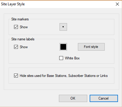
Site Layer Style
Site Layer Style
Show
Show / hide
Site Markers
Select a marker for sites from the standard set.
Site Name Labels
Choose font type, style, and color for site names.
White Box
Place the label on a white box
Hide Sites used for Base Stations, Subscriber Stations, or Links
Hide sites that are already used to host Base Stations, Subscriber Stations, or Links. Only empty sites will be shown on the base map.
PtP Link Layer Style

PtP Link Layer Style
Show only Active Links
Show only active links.
Show all Links
Show all links.
Site Markers
Show / hide, as well as select a marker for the ends of the link from the standard set.
Site Name Labels
Show / hide the name of the ends of the link, as well as choose the font style and color.
White Box
Place the label on a white box
Link Lines
Show / hide the link, as well as select the color and line thickness.
PtMP Base Stations Layer Style

PtMP Base Stations Layer Style
Show only Base Stations with Active Sectors
Show all Base Stations
Show / Hide Site Markers
Show / Hide Site Name Labels
White Box
Show / Hide Sector Lines
Show / Hide Sector Azimuth Labels
Show only base stations with active sectors.
Show all base stations.
Show / Hide and also select the marker for the base station from the standard set.
Show / Hide base station label, as well as select font style and color.
Place the label on a white box
Show / Hide base station sector designation, as well as select color and line thickness.
Show / Hide sector labels, as well as select font styles and colors for them.
Subscriber Station Layer Style

Subscriber Station Layer Style
Show only Subscriber Stations for Active Sectors
Show all Subscriber Stations
Show / Hide Site Markers
Show / Hide Site Name Labels
White Box
Show / Hide Point-to-Multipoint Link Lines
Show only Subscriber stations for active sectors.
Show all subscriber stations.
Show / Hide and also select the marker for the subscriber station from the standard set.
Show / Hide subscriber station label, as well as select font style and color.
Place the label on a white box
Show / Hide the point-to-multipoint link lines, as well as select their colors and line thickness.
Custom Layer Style

Custom Layer Style
Point Markers
Point Labels
Polylines
Show / Hide and also select the marker of point features from the standard set.
Show / Hide the point features label and also select the font style and color.
Show / Hide polylines, as well as select the colors and thickness of polylines.
Settings

Settings
Coordinate Format
Geographic coordinate format:
-
Decimal Degrees (N44.345678 W134.567893)
-
Degrees, Minutes, Seconds (N44 34’ 23.7’’ W134 29’ 23,4’’)
-
Degrees, Decimal Minutes (N44 34.2356’ W134 29.2354’)
Coordinate System
Coordinate System:
-
WGS-84
-
СК-42 (Russia)
-
ГСК-2011 (Russia)
Step of Terrain and Obstacle Points along the Profile, m
The step of terrain and obstacle points along the profile for automatic creation of the path profile.
For SRTM-1, the minimum step for creation of the path profile is 30 m. A lower value makes no sense since it will not increase the accuracy.
Part of first Fresnel Zone which will be Shown, %
A part of the first Fresnel zone which will be shown when the path profile is displayed.
Median Value of K-factor
The median value of the k-factor that will be used to create the link path profile and determine clearance
Distance and Height Units
Distance and Height Units:
-
Metric (kilometers, meters)
-
English (miles, feet)
Path to Folder with Cache Files
The path to the folder where downloaded base map tiles will be saved for quick access. This will speed up the application. The downloaded maps will remain on your computer and you will be able to view them when you do not have an Internet connection. This folder is created automatically when the application is launched for the first time. You can change this folder.
Path to Folder with Data Files
The path to the folder where the downloaded SRTM and forest data files will be saved for quick access. This will speed up the application. Moreover, the downloaded files will remain on your computer and the application will be able to use them and create a terrain profile when you don’t have an Internet connection. This folder is created automatically when the application is launched for the first time. You can change this folder.
Proxy Settings
If you are using a proxy server to access the Internet, enter its IP-address and port number. If the proxy server requires authentication, enter the username and password.
Custom elevation GeoTiff file
In order to use custom DEM, specify the path to it in the Settings menu and check the "Use custom elevation Geo Tiff file" box. File format requirements are outlined in Appendix 2 "Custom DEM Format".
Place the Base Station, Subscriber Station, or Link in the Map Center when you Click on them
Place the base station, subscriber station, or link in the map center when you click on them.
Enable "Show / Hide Panel Buttons" in the Main Toolbar
Enable "Show / Hide panel buttons" in the main toolbar.
Basemap Settings
You can configure your own custom base map in MLinkPlanner by specifying a tile server URL. The prototype URL encapsulates a request format that is specific to the map provider and varies from provider to provider. It consists of a text string that begins with http://, has a domain name and possible parameters, plus some symbols that MLinkPlanner substitutes with real-time tile request information when actually contacting the server.
The possible symbols that MLinkPlanner accepts in the prototype URL are [X], [Y], and [Z] coordinates and zoom. To lookup map imagery in their database, most map providers use tile coordinates of x and y, plus zoom. For example, OpenStreetMap provides map imagery using x, y, and zoom. You can test-fetch a map tile of a portion of North America by typing the following URL into a web browser: http://a.tile.openstreetmap.org/3/1/2.png. The numbers at the end of the URL represent zoom, x, and y, respectively.
In order for MLinkPlanner to properly fetch tiles from a map provider, a generalized prototype URL scheme must be furnished. This generalized URL scheme will be used by MLinkPlanner to fetch any tile, at any coordinate, with any zoom. To accomplish this, the symbols [X], [Y], and [Z] are inserted in place of explicit coordinates. For example, creating custom map types in MLinkPlanner for OpenStreetMap can be accomplished by mixing the known explicit URLs above with the symbols representing x, y, and zoom to form a custom map prototype URL: http://a.tile.openstreetmap.org/[Z]/[X]/[Y].png. When MLinkPlanner needs a map tile fetched from a provider, it will replace the [X], [Y], and [Z] symbols with the actual coordinates and zoom for the tile required and then use the resulting URL to contact the map provider’s server to fetch the map tile.
Appendix 1. Default DEM
North America
1 Arc-second Digital Elevation Model USGS National Map 3DEP
Coverage: USA, Canada, Mexico.
Source: https://data.usgs.gov/datacatalog/data/USGS:35f9c4d4-b113-4c8d-8691-47c428c29a5b
Europe
We use open digital terrain models (DTM) from national geoservices for the following European countries:
-
Austria (DTM 5-10 meters)
-
Belgium (DTM 5-10 meters)
-
Czech (DTM 1 meter)
-
Denmark (DTM 2 meter)
-
Estonia (DTM 10 meters)
-
Finland (DTM 10 meters)
-
France (DTM 5-10 meters)
-
Germany (DTM 2-10 meters)
-
Iceland (DTM 10 meters)
-
Ireland (DTM 2 meter)
-
Italy (DTM 2-10 meters)
-
Latvia (DTM 20 meters)
-
Lithuania (DTM 5 meters)
-
Liechtenstein (DTM 10 meters)
-
Luxembourg (DTM 0.5 meter)
-
Netherlands (DTM 5 meters)
-
Norway (DTM 10 meters)
-
Poland (DTM 1 meters)
-
Portugal (DTM 0.5-10 meters)
-
Romania (DTM 1 meter)
-
Slovakia (DTM 1 meter)
-
Slovenia (DTM 1 meters)
-
Spain (DTM 2-5 meters)
-
Sweden (DTM 50 meters)
-
Switzerland (DTM 2 meters)
-
United Kingdom (DTM 2 meters)
For the rest of Europe, we use the European Digital Elevation Model (EU-DEM), version 1.1.
Coverage: Albania, Bosnia and Herzegovina, Bulgaria, Croatia, Cyprus , Greece, Hungary, Kosovo, Malta, Montenegro, North Macedonia, Serbia, Turkey.
Source: https://land.copernicus.eu/imagery-in-situ/eu-dem/eu-dem-v1.1?tab=metadata
Australia
SRTM-derived 1 Second Digital Elevation Models Version 1.0 (DEM-S).
Coverage: Australia
Source: https://ecat.ga.gov.au/geonetwork/srv/eng/catalog.search#/metadata/72759
New Zealand
New Zealand National Digital Elevation Model a 25-meter resolution.
Coverage: New Zealand
Source: https://lris.scinfo.org.nz/layer/48131-nzdem-north-island-25-metre/
South America, Africa, Asia, Middle and Far East regions
ALOS World 3D - 30m (AW3D30) by the Japan Aerospace Exploration Agency’s (JAXA).
Appendix 2. Custom DEM Format
Starting from update 221121, MLinkPlanner 2.0 allows users to use their own Digital Elevation Model (DEM) in GeoTIFF format. GeoTIFF is a public domain metadata standard that enables georeferencing information to be embedded within an image file1. Elevation data from a LiDAR survey or any other DEM can be converted to the GeoTIFF format using specialized GIS applications such as QGIS, Global Mapper, ArcGis, MapInfo, and others.
Custom DEM must consist of a single Geo TIFF file (not tiles) with the following settings:
File Type: Int16 (Sixteen-bit signed integer)
Compression: No/LZW/Deflate (ZIP)
Projection: Geographic (Latitude/Longitude)
Datum: WGS84
Planar Units: ARC Degrees
Vertical Units: Meters
Max Width x Height: 100 000 x 100 000 points (for 64 GB RAM and powerful CPU). For comfortable work on a computer of average performance, we do not recommend making the DEM size larger than 50,000 by 50,000 points.
Some custom DEM samples in Geo TIFF format can be found in the installation folder.
An example of exporting to a Geo TIFF file in the Global Mapper DEM program with a resolution of 1/5 arc second (0.00005555 arc degree):
