RadioPlanner 3.0
Mobile and Broadcast Network Planning Software
User Manual


Download in PDF format
We have made every effort to create a user-friendly and intuitive application. However, we recommend taking some time to read this User Manual to fully utilize RadioPlanner’s capabilities. Created by engineers with over 25 years of experience in designing radio communication and broadcasting networks, RadioPlanner is a full-featured yet simple and convenient planning tool.
Features
RadioPlanner 3.0 is a planning tool for various types of networks, including:
- Mobile networks: 5G (NR), LTE, UMTS, GSM, GSM-R, WCDMA. This is a great tool for planning private 5G/4G networks.
- Public safety land mobile networks: P25, TETRA, DMR, dPMR, NXDN
- Wireless IoT LPWAN networks: LoRa, SigFox, LTE NB-IoT Cat-M1/Cat-NB1/Cat-NB2
- Precision agriculture systems
- Terrestrial television and radio broadcast networks: ATSC 1.0, ATSC 3.0, DVB-T/T2, ISDB-T, DTMB, DAB+, HD Radio, FM
- Air-to-ground communication and radio navigation systems operating in VHF, UHF, and microwave frequencies: UAV (Drone) Control, Air-to-ground radio, ADS-B, VOR, DME
RadioPlanner 3.0 uses propagation models:
- ITU-R P.1812-6
- ITU-R P.1546-6
- Longley-Rice (ITM) v1.2.2
- Okumura-Hata
- 3GPP TR 38.901
- Combined ITU-R P.528-3 + P.526-14 (for Ground-to-Air Radio only)
RadioPlanner 3.0 performs various types of area studies for mobile networks:
- Received Power
- Best Server (Strongest Server)
- C/(I+N) Ratio
- Maximum Throughput
- Maximum Aggregated Throughput
- Area with Signal above Both Base and Mobile Thresholds
- Number of Servers
- Coverage Probability
- Reference Signal Received Power (RSRP) for 5G and LTE
- Energy Per Resource Element (EPRE) for 5G and LTE
- Reference Signal Received Quality (RSRQ) for 5G and LTE
- Simulcast Delay Spread
- Received Power with Simulcast Interference
- TalkOut and TalkBack
- Field Strength
Area studies for terrestrial radio and television broadcast transmitters include:
- Field Strength at Receiver Location
- Best Server
- Simulcast Delay Spread
- FCC contours
- ITU-R P.1546-6 contours
- Population coverage
- Generation of list of localities covered by broadcasting
Area studies for Air-to-Ground radio communication systems include:
- Received power Air-to-Ground link
- Received power Ground-to-Air link
- Best Server Air-to-Ground link
- Best Server Ground-to-Air link
RadioPlanner offers the following features:
- Work with multiple networks within a single project and view aggregate coverage predictions for maximum throughput and number of servers.
- Plan radio network frequencies while considering co-channel and adjacent channel interference.
- Display of path profiles with path losses and levels of carrier and interference on the co-channel and adjacent channels.
- Perform multipoint study of a group of CPE or IoT sensors (end devices), each with their individual parameters (antenna height, antenna gain, transmitter power, cable loss, and penetration loss) under varying deployment conditions.
- Import measured signal power level results for comparison with calculated values and adjust propagation model parameters.
- Compare multiple coverage prediction results.
- Save coverage prediction results as an interactive web page, KMZ file, PNG image, GeoTiff file, CSV file or as MIF file.
- Flexibly adjust base map layers and display custom vector layers.
GIS features:
- Default digital terrain model (DTM) with 30m plane resolution, automatically loaded worldwide (see Appendix 2 for data source details).
- Option to use custom DTM in GeoTiff format.
- Default clutter model with nine clutter types, automatically loaded worldwide. Created from OpenStreetMap (www.openstreetmap.org) and Global Forest Change projects.
- Option to use custom clutter in GeoTiff format.
- Common (e.g., OpenStreetMap, OpenTopoMap, US Topo) and custom base maps.
Installation and Activation
RadioPlanner is compatible with 64-bit Windows 8/8.1/10/11. The minimum computer requirements include a 64-bit Windows operating system, Core i3 CPU, 4GB RAM, 200GB HDD, video card, and monitor with support for 1366x768 resolution. For optimal performance, it is recommended to use a computer with a 64-bit Windows operating system, Core i5 CPU, 16GB RAM, 256GB SSD, video card, and monitor with support for 1920x1080 resolution. Additionally, Microsoft Excel must be installed on the computer to use all RadioPlanner features.
To access the full version of RadioPlanner, a license must be purchased. After successful purchase, an email will be sent containing a link to download the full version installation file and an Activation ID for the license. Follow the instructions in the installation file and enter the Activation ID when prompted to activate the fully functional version of RadioPlanner.
Software Update
We periodically release free updates to improve the functionality and stability of RadioPlanner. The software supports both manual and automatic checking for updates and will check for available updates every time it starts. To check for updates manually, click “Help - Check for updates.” If an update is available, a window will open with information about the current and available versions. You can download the update from the provided link and install it manually. Be sure to exit RadioPlanner before installing the update.
User Interface
After starting the program, the main panel will appear with the main menu on the left side and the base map on the right side. The size of the panels can be adjusted using the separator. The base map can display various layers, including sites, coverage, terrain and clutter layers, base map, and additional vector layers. You can choose to display one of the pre-installed base maps or customize your own base map as described in the Base map Settings section.
Navigation on the map is done using the mouse, with the mouse wheel used to zoom in and out. You can also select the desired zoom level from the drop-down list in the toolbar.
Toolbar and Main Menu

Toolbar
When you hover over each of the icons, a hint appears.
Standard tools for working with files: Create, Open, Save
Save project
The zoom of the base map
- The base map
The “ruler” tool allows you to measure the distance and azimuth between any two points on the map. To use this tool, click on the ruler icon and then click on any two points on the map. The distance between the points and the azimuth from the first to the second point will be displayed. To exit the tool, right-click anywhere on the map.
Repeat previous coverage prediction
Add the coverage to compare
Show / Hide Legend
Save the map as WEB page
Save the map as an image in PNG format
Save the map as KMZ file
Save the map as GeoTiff file
Save coverage in GIS format
Searh sites by the name
Run Noise-Adjusted Faded Performance Threshold Calculator
Help
For more detailed information about each tool, please refer to the corresponding sections in the User Manual.

Tree View interface
Project Information
A new project is automatically created when RadioPlanner is launched. The File menu contains standard buttons (New, Open, Save, Save As) for performing standard file operations. Project files can be saved with the *.rp3 extension and contain all information about the project.
General information about the project can be specified in the project information panel.

Project Information
Project name
Customer
Date
Logo
Exclude from Legend
Text field
Text field
Text field - When creating a new project, it records the date and time of the project creation
Your company logo. The recommended resolution is approximately 270 by 60 pixels.
Exclude corresponding lines from Legend
Settings
Before starting to work with the software, it is necessary to configure the settings.


Settings
Distance and Height Units
- Metric
- English
Coordinate Format
- Decimal Degrees (N44.345678 W134.567893)
- Degrees, Minutes, Seconds (N44 34' 23.7" W134 29' 23,4")
- Degrees, Decimal Minutes (N4434.2356' W134 29.2354')
Path to Folder with Cache Files
The path to the folder where downloaded base map tiles will be saved for quick access can be specified in the settings. This folder is created automatically when the application is launched for the first time and can be changed if desired. The downloaded maps will remain on your computer and can be viewed even when you do not have an Internet connection.
Path to Folder with Data Files
The path to the folder where downloaded default Digital Terrain Model (DTM) and default clutter model files will be saved for quick access can be specified in the settings. This folder is created automatically when the application is launched for the first time and can be changed if desired. The downloaded files will remain on your computer and can be used by the application to create a terrain profile even when you do not have an Internet connection.
Proxy Settings
If you are using a proxy server to access the Internet, enter its IP address and port number in the Proxy Settings section. If the proxy server requires authentication, enter the username and password.
Base Map Settings
You can configure your own custom base map by specifying a tile server URL. This URL encapsulates a request format specific to the map provider and consists of a text string that begins with http:// and includes a domain name, possible parameters, and symbols that RadioPlanner substitutes with real-time tile request information when contacting the server.
The symbols that RadioPlanner accepts in the prototype URL are [X], [Y], and [Z] coordinates and zoom. Most map providers use tile coordinates of x and y, plus zoom to lookup map imagery in their database. For example, OpenStreetMap provides map imagery using x, y, and zoom. To fetch a map tile of a portion of North America, you can enter the following URL into a web browser: http://a.tile.openstreetmap.org/3/1/2.png. The numbers at the end of the URL represent zoom, x, and y respectively.
To create custom map types in RadioPlanner for OpenStreetMap, you can mix the known specific URLs with the symbols representing x, y, and zoom to form a custom map prototype URL. For example: http://a.tile.openstreetmap.org/[Z]/[X]/[Y].png. When RadioPlanner needs to fetch a map tile from a provider, it will replace the [X], [Y], and [Z] symbols with the actual coordinates and zoom for the required tile and use the resulting URL to contact the map provider’s server to fetch the map tile.
To use custom maps, enter the Map Server’s URL of the desired map. You can search online for local map providers’ map servers’ URLs. If you have more relevant or detailed cartographic data for the desired territory in the form of an image or vector map, you can create your own tile server using specialized GIS software such as MapInfo, QGIS or Global Mapper.
Download latest base map settings
Apply base map settings
Update basemap settings from our server. User tile server addresses will be removed
Apply basemap settings after entering custom tile server address
Geo Data
This menu allows you to specify the geodata (DTM and clutters) that will be used in calculations.

Geo Data Parameters
Digital Terrain Model (DTM)
The Digital Terrain Model (DTM) is a geographic data file (or files) representing the elevation of the ground above sea level. In RadioPlanner 3, you can use the default DTM that is automatically downloaded from our server when predicting coverage. This DTM is compiled from open geodata sources and is available worldwide. It is sufficient for most use cases.
Alternatively, you can use custom DTMs in GeoTiff format. GeoTIFF is an open format that can be used to convert elevation data from a LiDAR survey or any other DTM. This conversion can be performed using specialized GIS applications such as QGIS, Global Mapper, ArcGis, MapInfo, and others.
Use default DTM
Use custom DTM
Use default DTM
Use custom elevation DTM. Import the DTM file(s) in Geotiff format.
Custom DTM GeoTIFF files(s) must have the following format:
File Type: Int16 (Sixteen-bit signed integer)
Compression: No/LZW/Deflate (ZIP)
Projection: Geographic (Latitude/Longitude)
Datum: WGS84
Planar Units: ARC Degrees
Vertical Units: Meters
An example of exporting to a DEM Geo TIFF file in the Global Mapper with a resolution of 1/5 arc second (0.00005555 arc degree):

An example of configuring DTM export settings to Geotiff
Max Width x Height: 100 000 x 100 000 points (for 64 GB RAM and powerful CPU). For comfortable work on a computer of average performance, we do not recommend making the DEM size larger than 50,000 by 50,000 points.
Some custom DTM samples in GeoTIFF format can be found in the installation folder.
On our YouTube channel, we have posted a video on preparing custom DTM: https://youtu.be/yS2dQreh3Cs
Custom DTM
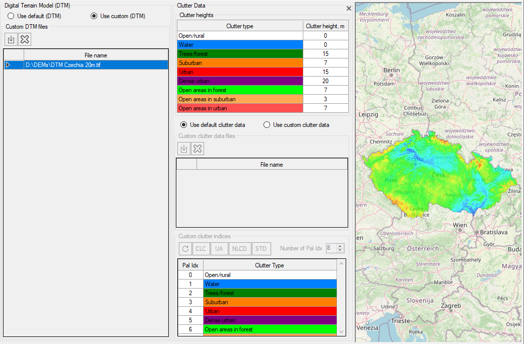
Clutter Data
The clutter data describes land cover or land use and is used by RadioPlanner to calculate signal power loss on local obstacles surrounding the mobile unit.
In RadioPlanner 3, you can use the default clutter data that is automatically downloaded from our server when predicting coverage. This data is compiled from open geodata sources (OpenStreetMap and Global Forest Change projects) and is available worldwide. It is sufficient for most use cases.
The clutter model used in RadioPlanner has 9 types of clutters:
1
2
3
4
5
6
7
8
9
Clutter Type
Color
Open / Rural
Water
Trees / Forest
Suburban
Urban
Dense Urban
Open areas in forest
Open areas in suburban
Open areas in uburban

Description
Open and rural area
Water area
Forest area
Suburban area
Urban area
Dense urban area
Forest roads
Highways, wide roads
Highways, avenues, wide roads
For each clutter type, you can specify an average height (used to calculate clutter loss in the ITU-R P. 1812-6 propagation model) or directly enter the loss value (see the Propagation Model menu).
Clutter heights
The typical clutter height. This value is used in the ITU-R P.1812 and ITU-R P.1546 recommendations to calculate clutter loss.
Use default clutter data
Use custom clutter data
Use default clutter
Import the clutter file(s) in Geotiff format.
You can also use custom clutter data in GeoTiff 8-bit Palette Image file format. Each pixel of this file can contain up to 256 possible clutter classes (commonly used up to 30), representing specific types of land use or landcover. Custom clutter files can be prepared from a land use database (e.g., NLCD, CORINE, ESA Global Land Cover) using specialized software (Global Mapper, QGIS, MapInfo, etc.).
Custom clutter indices
Clutter file palette indices to clutter type correspondence table
CLC - CORINE Land Cover https://land.copernicus.eu/pan-european/corine-land-cover
UA – CORINE Urban Atlas https://land.copernicus.eu/local/urban-atlas/urban-atlas-2018
NLCD - National Land Cover Database https://www.usgs.gov/centers/eros/science/national-land-cover-database
Default - Deafaul clutter indices (0,1,2,3,4,5,6,7,8)
Number of Pal Idx
Number of indexes in custom palette
After importing a custom clutter file into RadioPlanner, it is necessary to establish a correspondence between its palette indexes and the 9 clutter types used in the program. We have made lookup table presets for some standard land cover types (NLCD, CORINE Land Cover, CORINE Urban Atlas). To use these presets correctly, you need to use a special standard (for NLCD and CORINE Land Cover) or custom (for CORINE Urban Atlas) palette when exporting to GeoTiff. Some custom clutter data file samples in GeoTiff format can be found in the installation folder.
On our YouTube channel, we have posted a video on preparing custom clutter from several common landcover types:
https://youtu.be/5QWYYGhGEdY How to make custom clutter from National Land Cover Database (NLCD)
https://youtu.be/pmY6YNy3eIo How to make custom clutter from CORINE Land Cover
https://youtu.be/DwBRa2g2VIA How to make custom clutter from Urban Atlas
Custom clutter GeoTIFF file(s) must have the following format:
File Type: 8-bit Pallete Image
Compression: No/LZW/Deflate (ZIP)
Projection: Geographic (Latitude/Longitude)
Datum: WGS84
Planar Units: ARC Degrees
Max Width x Height: 100 000 x 100 000 points (for 64 GB RAM and powerful CPU). For comfortable work on a computer of average performance, we do not recommend making the clutter size larger than 50,000 by 50,000 points.
An example of exporting to a clutter Geo TIFF file in the Global Mapper:

An example of configuring clutter export settings to Geotiff

Custom Clutter
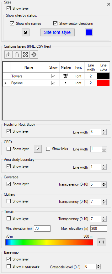
Map Layers
In the Map Layers menu, you can control which layers are displayed on the map. The order of the layers in the menu corresponds to their order on the map, with the base map at the bottom and sites at the top of all layers.
Map Layers
Sites
Sites are Base Stations or transmitters for TV and radio broadcasting.
Show layer
Show only active sites
Show site names
Show sector directions
Site marker
Site font style
Show/hide site layer
Show only active sites
Show site names
Show sector direction according to antenna azimuth
Choose marker for sites
Change font type for sites
Custom Layers (KML, CSV)
You can load and display point or linear vector objects in KML format as a layer on the map. This can include objects such as power lines, piping, and etc. Custom layers are saved in the project file.
Name
Show
Marker
Line width
Line color
Load a custom layer (KML, CSV file)
Save points from the selected layer to a CSV file
Delete selected custom layer
Position the map on the first point of the selected layer
The name of the user layer. Initially corresponds to the file name, but can be changed
Show/hide custom map layer
Select a marker for the item (only for point objects)
Specify line width (only for line)
Specify line color (only for line)
Point objects can also be downloaded from a CSV file (text format with a semicolon separator).
Each point object must have the required fields of Parameter, Latitude, and Longitude. Coordinates can be formatted as HEMISPHERE degrees minutes seconds (N35 23.8 36) or HEMISPHERE decimal degrees (N12.34567). The parameter can be any text that appears at the specified coordinates, such as a measurement result or the name of an object.

Sample CSV file with Antenna Towers

Custom Layer on the map
You can also quickly create point objects directly on the map. To do this, right-click on the desired location and select “Add a new point to the ‘Custom Points’ layer” from the context menu. Then specify the point name and it will appear on the map and be added to the “Custom Points” layer, which is automatically created when you create the first point object. You can also delete created point objects by right-clicking on the point and selecting “Delete the nearest point in the ‘Custom Points’ layer” from the context menu.


Adding a point feature to a map
Routs for Route Study
Routs layer control. For more details, see the section on Miscellaneous Studies - Route Study.
Show layer
Show/hide Routs layer
Line width
Line width
CPEs
CPE map layer control. CPE is customer premises equipment for fixed wireless access (FWA) applications or Sensors for IoT networks such as LoRaWAN, SigFox and others.
Show layer
Show/hide CPE layer
Select marker
Choose marker for CPEs
Show links
Show link to the assigned BS sector
Line width
Line width
Area Study Boundary
The area study boundary map layer control.
Show layer
Show/hide layer
Line width
Line width
Coverage
The coverage prediction map layer control.
Show layer
Transparency
Show/hide layer
Set layer opacity in the range from 0 (fully transparent) to 10 (not transparent)
Clutter
The clutter map layer control.
Show layer
Show / Hide the сlutter map layer. The default clutter is shown only for zoom 11 and higher. A сustom clutter is shown for any zoom.
Transparency
Layer opacity in the range from 0 (fully transparent) to 10 (not transparent)
Terrain
The Terrain map layer control.
Show layer
Show / Hide the terrain map layer. The default terrain is shown only for zoom 9 and higher. A сustom terrain is shown for any zoom.
Transparency
Min (Max) Elevation
Layer opacity in the range from 0 (fully transparent) to 10 (not transparent)
Elevation legend range. All heights below the minimum (including the minimum) will be fully transparent. All heights above the maximum will be in maroon.
Set the minimum and maximum height on the screen. Sets the height range within the minimum and maximum heights found within the screen.
Base Map
Base map layer control.
Show layer
Show/hide the layer
Show in grayscale
Show base map in grayscale
Grayscale level
Brightness from the range 0 (darker) - 3 (lighter)
RF Planning for Mobile Networks
RadioPlanner 3.0 allows you to work with multiple networks in one project. When creating a new project, the first network is created by default.

Networks menu
Add a new network
Calculate Coverage (See Coverage predictions for multiple networks section)
Area Study Type
Coverage predictions for multiple networks:
- Number of Networks (DL)
- Number of Networks (UL)
- Maximum Aggregated (DL) Throughput
- Maximum Aggregated (UL) Throughput
See Coverage predictions for multiple networks section
Area Study Resolution for all study types
Coverage prediction resolution. Specifies the details of both aggregated calculations and calculations for each of the networks.
- Low
- Medium
- High
The resolution corresponds to one pixel of the screen for zoom = 11 (low detail), zoom = 12 (medium), and zoom = 13 (high). For a geographic latitude of 55 degrees, this is approximately 40, 20, and 10 meters, respectively.
The higher the resolution, the longer the calculation time.
Mobile Unit (UE) №1/№2
Select the mobile device for which the calculation will be made
Network
The “Network” menu is used to set all parameters for the selected network, including mobile station parameters and calculation parameters. You can also perform calculations for the network using this menu.

Network menu
Add a new network with the same parameters (copy the network)
Check/Uncheck all sectors for current network
Move the Network up
Move the Network down
Delete the network
System parameters
Calculate Coverage
Calculate FWA Coverage taking into account the parameters of each CPE. See section "Fixed Wireless Access network"
Calculate coverage for each active sector and save the map as a KMZ file
Load network parameters from a template
Save network parameters as a template
Create network sectors based on the selected sectors of the other network
Network name
System type
Downlink
Uplink
Downlink Rx threshold
Uplink Rx threshold
Study radius
Name of network, text field
System type options:
- Generic TRX
- LTE
- 5G
- Terrestrial Broadcasting
- Air-to-Ground Radio
The selected system type will determine the set of additional system parameters, as well as the types of coverage predictions available.
Average downlink frequency, MHz
Average uplink frequency, MHz
This threshold value will limit the coverage prediction display based on whether the signal received at the mobile unit from the base station is above or below this threshold, dBm
This threshold value will limit the coverage prediction display based on whether the signal received at the base station from the mobile unit is above or below this threshold, dBm
Maximum study radius, km The larger the radius, the longer the computation time. Do not set an unnecessarily large calculation radius.
Mobile Units
Type
TX Power
Cable and Connector Loss
Antenna Height
Antenna Gain
Use directional antenna pattern for Mobile Unit (UE)
Name (model) of Mobile Unit, text field
Transmitter power, W
Loss in cable and connectors, dB
Antenna height relative to ground level, m
Antenna gain, dBi
By default, the mobile units' (UE) antenna pattern is assumed to be isotropic. If you are designing a fixed wireless access (FWA) network with directional CPE antennas, you should download the antenna pattern in MSI format. It is assumed that the CPE antennas are aimed at the BS sector with the strongest signal at the CPE location.
The use of directional antennas on the CPE significantly reduces interference from neighboring cells and, as a result, increases CPE throughput.
RadioPlanner allows you to predict coverage for two types of mobile devices. This is used in professional mobile radio networks, where portable and mobile stations are often used, since they differ in both power characteristics and antenna height relative to ground level. Also, coverage prediction for several types of mobile devices with different antenna heights is often necessary in fixed wireless access (FWA) networks.
LTE System Parameters
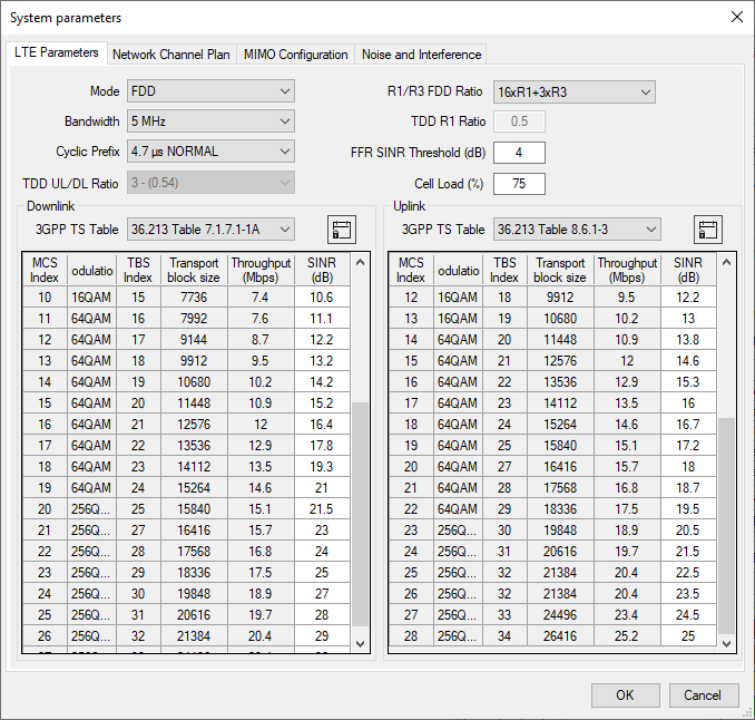
LTE System Parameters
Mode
LTE duplex mode:
- FDD
- TDD
Bandwidth
Cyclic Prefix
TDD UL/DL Ratio
R1/R3 FDD Ratio
TDD R1 Ratio
FFR SINR Threshold
Cell Load
Downlink and Uplink 3GPP Tables
LTE bandwidth: 1.4 MHz; 3 MHz; 5 MHz; 10MHz; 15 MHz; 20 MHz
LTE Cyclic Prefix:
- 4.7 µs (Normal)
- 16.7 µs (Extended)
TDD configurations in 3GPP LTE specification:
TDD Configuration # UL/total ratio DL/total ratio
0 0.7 0.3
1 0.5 0.5
2 0.3 0.7
3 0.35 0.65
4 0.25 0.75
5 0.15 0.85
6 0.6 0.4
Type of Fractional Frequency Reuse (FFR) plan that is being used in LTE project in the R1/R3 zone Resource Blocks drop-down list
Part (from 0.1 to 1) the R1 zone subcarriers of physical resource blocks (PRB) for TDD
SINR threshold for switching between R1 and R3 zones in FFR, dB
Cell Load, 0-100 % Cell Loading is considered uniform. The possibility of different cell loading by sectors and the use of subscriber density maps will be added in the future.
These tables contain the MCS Index, modulation type, and transport block size (TBS) specified in the tables of 3GPP TS 36.213 and for Narrowband LTE IoT Cat-M1/LTE Cat-NB1/LTE Cat-NB2 standards. Minimum C/(I+N) values for 1% SER (dB) can be specified separately for both uplink and downlink. The theoretical defaults shown in this table are from published MATLAB simulations of LTE radio link performance. The throughput for each modulation index is determined from the 3GPP tables, taking into account the transport block size. This throughput does not take into account the MIMO multiplier.

Parameters for Narrowband LTE IoT
Network Channel Plan
In the channel table, specify all possible uplink and downlink frequencies (channels) that will be used in the network. For TDD, enter the same frequency. If the network operates on a single channel, then the frequencies in the Network Channel Plan may not be specified.

LTE Network Channel Plan
MIMO Configuration
The MIMO table is fully configurable for all downlink and uplink scenarios.
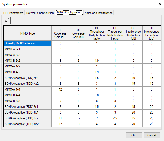
LTE MIMO Configuration
Noise and Interference
The receiver parameters in this tab are used for noise and interference calculations.

LTE Noise and Interference
Rx equivalent noise bandwidth
Receiver Equivalent Noise Bandwidth, MHz
In LTE systems, when using all resource blocks, the following noise bandwidths are obtained:
1.08 MHz (1.4 MHz Bandwidth)
2.7 MHz (3 MHz Bandwidth)
4.5 MHz (5 MHz Bandwidth)
9 MHz (10 MHz Bandwidth)
13.5 MHz (15 MHz Bandwidth)
18 MHz (20 MHz Bandwidth)
Rx noise figure
Rx noise level
Adjacent channel rejection
Receiver noise figure, dB Typically 3-4 dB for eNodB and 6 dB for UE
Receiver noise level, dB This value is used to estimate the noise on the receiving path when calculating all types of interference.
Adjacent channel rejection, dB It is assumed that the receiver has a rectangular “brick wall” bandpass shape with a width equal to the equivalent noise bandwidth. Under these conditions, you can set the amount of attenuation on adjacent channels (one bandwidth above and below the desired bandwidth) by entering a value here for adjacent channel rejection.
5G (NR) System Parameters

5G Parameters
Mode
Duplex mode:
- FDD
- TDD
Configuration
Downlink and Uplink 3GPP Tables
Choice from bandwidth (BW) and Subсarrier Spacing (SCS) configurations.
These tables contain the MCS Index, modulation type, and Target code rate specified in the tables of 3GPP TS 36.214. Minimum C/(I+N) values for 1% SER (dB) can be specified separately for both uplink and downlink. The theoretical defaults shown in this table are from published MATLAB simulations of 5G radio link performance. The throughput for each modulation index is determined from the 3GPP tables. This throughput does not take into account the MIMO multiplier.
DL symbols part in TDD slot (0..1)
Part of the TDD resource that is intended for downlink
Cell Load
Cell Load, 0-100 % Cell Loading is considered uniform. The possibility of different cell loading by sectors and the use of subscriber density maps will be added in the future.
Network Channel Plan
In the channel table, specify all possible uplink and downlink frequencies (channels) that will be used in the network. For TDD, enter the same frequency. If the network operates on a single channel, then the frequencies in the Network Channel Plan may not be specified.

5G Network Channel Plan
MIMO Configuration
The MIMO table is fully configurable for all downlink and uplink scenarios.
5G MIMO Configuration
Noise and Interference
The receiver parameters in this tab are used for noise and interference calculations.

5G Noise and Interference
Rx equivalent noise bandwidth
Receiver Equivalent Noise Bandwidth, MHz
In 5G, the noise band can be obtained from the formula:
Rx equivalent noise BW= 12*SCS*Resource Blocks.
For example, for BW=100 MHz, SCS=30 kHz
Rx equivalent noise BW=12*0.03*273=98.28 MHz
Rx noise figure
Rx noise level
Adjacent channel rejection
Receiver noise figure, dB Typically 3-4 dB for eNodB and 6 dB for UE
Receiver noise level, dB This value is used to estimate the noise on the receiving path when calculating all types of interference.
Adjacent channel rejection, dB It is assumed that the receiver has a rectangular “brick wall” bandpass shape with a width equal to the equivalent noise bandwidth. Under these conditions, you can set the amount of attenuation on adjacent channels (one bandwidth above and below the desired bandwidth) by entering a value here for adjacent channel rejection.
Generic TRX System Parameters
Generic TRX in RadioPlanner includes all mobile communication systems except for LTE and 5G:
- UMTS / GSM / GSM-R / WCDMA mobile networks
- P25 / TETRA / DMR / dPMR / NXDN land mobile radio networks
- Networks based on wireless IoT LPWAN technologies: LoRa, SigFox, and others
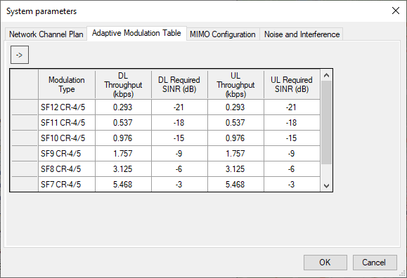
Adaptive Modulation Table
The adaptive modulation table is filled with SINR values and their respective throughput. This table is used to predict downlink and uplink throughput in Generic TRX. Note that LTE and 5G have separate adaptive modulation tables tied to 3GPP specifications.
LoRaWAN Adaptive Modulation Table
Modulation Type
DL Throughput (kbps)
DL SINR (dB)
UL Throughput (kbps)
UL SINR (dB)
Modulation Type (text field)
Downlink Throughput, kbps
Downlink SINR,dB
Uplink Throughput, kbps
Uplink SINR,dB
Network Channel Plan
In the channel table, specify all possible uplink and downlink frequencies (channels) that will be used in the network. For TDD, enter the same frequency. If the network operates on a single channel, then the frequencies in the Network Channel Plan may not be specified.

Generic TRX Network Channel Plan
Sort frequencies in ascending order
Autofill downlink frequencies
Autofill uplink frequencies
If your network has a large frequency grid, then you can use the autofill feature:

Channel Autofill
MIMO Configuration
The MIMO table is fully configurable for all downlink and uplink scenarios.
Generic TRX MIMO Configuration
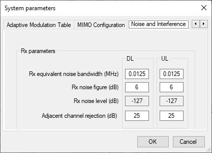
Noise and Interference
The receiver parameters in this tab are used for noise and interference calculations.
Generic TRX Noise and Interference
Rx equivalent noise bandwidth
Rx noise figure
Rx noise level
Adjacent channel rejection
Receiver Equivalent Noise Bandwidth, MHz
Receiver noise figure, dB Typically 3-4 dB for base station and 6 dB for Mobile Unit
Receiver noise level, dB This value is used to estimate the noise on the receiving path when calculating all types of interference.
Adjacent channel rejection, dB It is assumed that the receiver has a rectangular “brick wall” bandpass shape with a width equal to the equivalent noise bandwidth. Under these conditions, you can set the amount of attenuation on adjacent channels (one bandwidth above and below the desired bandwidth) by entering a value here for adjacent channel rejection.
Sites

Sites
Add a new site
Add a new site group
Import a site list from *.csv file
Sort sites in alphabetical order
Collapse of site nodes
Collapse all network nodes
Epand all site nodes
Delete all selected sites
Import site parameters from Microsoft Excel document
To create a new site, click on Sites in the Tree View interface, then click the "Add a new site" button in the panel that opens.
Import sites and sectors from *.CSV file
RadioPlanner 3.0 allows you to import base station and sector data from CSV files (a text format in which column values are separated by a semicolon or tab character). This is very convenient for a quick start, if the user already has a spreadsheet or database of sites and sectors.
You can save data from any spreadsheet editor (Excel, LibreOffice Calc, etc.) or databases to a CSV file.
Each line of this text file contains information about a separate sector in the following order:
Site Name; Latitude; Longitude; Network; Azimuth, deg; Sector Name; Antenna Height, m; Antenna model; Antenna Gain, dBi; Mechanical Downtilt, deg; Tx Power, W; Loss, dB
Only the first three fields of each line are required: Site Name; Latitude; Longitude. Other fields may be missing.
Coordinate representation formats: DEGREES MINUTES SECONDS OF THE HEMISPHERE (N35 36 23.8) or DECIMAL DEGREES OF THE HEMISPHERE (N12.34567). For the Southern and Western Hemispheres, you can use the "-" sign, and for the Northern and Eastern Hemispheres, do not specify the sign.
To correctly import network information from a file, you must first create networks with the same names in the project.
The "Losses, dB" field will be imported into the sector as "Additional losses".
If the folder with the imported file contains antenna pattern files in *.MSI format with a name that matches the Antenna model name in the CSV file, these patterns will be loaded into the corresponding sectors.
To import sites, click the "Import a list of sites from CSV file" button and select the corresponding CSV file, after which the program will perform the import. If the project already had sites, the imported sites will be added to the end of the list.
A sample CSV file is located in the Sample Data Files folder of the program installation package.
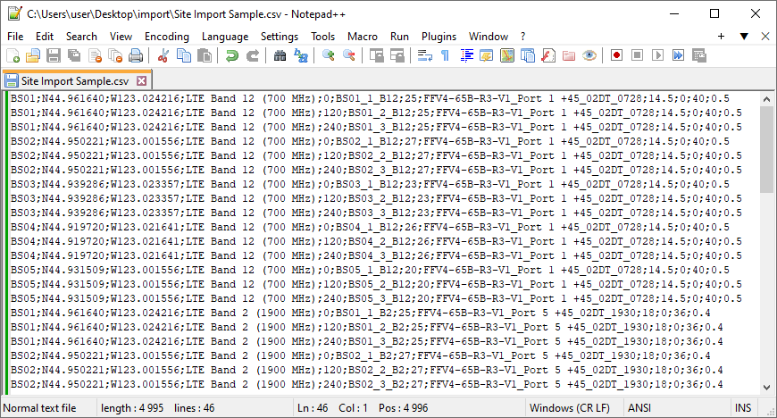
Sample of CSV file
Site Details
When clicking on a created site in the Tree View interface panel, the Site Details panel will open where you can edit details such as name, coordinates and additional text information about the site and view elevation relative to sea level.

Site Details
Add a new site as a copy of this site
Move site up or down
Delete the site
Load sectors of the selected network from a template
Save the sectors of the selected network as a template
Position the map with the site at the center of the screen
Copy Site Parameters to all active sites
Name
Site name, text field
Latitude
The geographical latitude of the site in the format specified by the user in Settings
Longitude
Geographical longitude of the site in the format specified by the user in Settings
Site Elevation
Site elevation relative to sea level, m
Notes
Text box for any additional site information
Group name
Select site group. Sites can be combined into groups (clusters), allowing you to quickly include/exclude large site groups of from calculations.
Sector Parameters
When creating a site, at least one sector of this site is automatically created. There is an activity icon next to each site and sector in the Tree View interface panel. For a sector to be calculated, it must be marked as active (a dot in the center). Clicking on the site sector will open a panel with the sector parameters.

Sector Parameters
Add a new sector with the same parameters
Move the sector up or down. These buttons are active for site Tree view structures "Sectors Only" and "Network | Sector"
Delete the sector
Global Active Sector parameters change. You can replace the selected parameters for all active sectors as the current sector.
Position the map with the site at the center of the screen
Advanced sector parameters
Analysis of measurements along the route. See more details in the "Measurement Results Analysis and Propagation Model Tuning" section.
Network
MIMO
Name
Radio Equipment
Set Rx Antenna and Transmission System to be the Same as Tx
Tx Power
Cable Type
Cable Length
Cable Loss
Additional Loss
Total Loss
Antenna Height
Antenna Gain
Azimuth
Beam Tilt
Antenna Model
The network to which the sector belongs, select from the drop-down list of networks.
MIMO type for the sector, selection from a drop-down list of all possible MIMO configurations specified in the system parameters of this network.
The name of the sector, the text field. You can specify the name of the sector in the text field. If left blank, the name “Sector azimuth” with the azimuth value specified in the sector parameters panel will be automatically displayed in the tree view panel on the left. If you specify a name in this field, it will be displayed in the tree view.
Name (model) of Radio equipment, text field
Copying parameters' antenna-feeder transmitter path to the receive path
Transmitter power, W. Same value in dBm for control
Type of the main cable for transmission or reception path. If the required cable is not in the list, then the user can add it himself - see Appendix 1.1
Main cable length, m
Loss in cable, dB. Calculated value
Additional losses, dB - combining losses, losses in jumpers, and connectors. Any additional losses.
Total loss, dB. The calculated value.
The antenna radiation center height relative to ground level, m
Antenna gain relative to isotropic radiator, dB When loading an antenna pattern from an MSI file, the antenna gain is also imported, taking into account the Gain Units in the file - dBi or dBd (of course, if the MSI file has this information).
The azimuth of the antenna in degrees
Tilt the antenna in degrees. Down is negative; up is positive.
Antenna name, text field. Automatically filled with the antenna pattern file name when selecting a pattern.
Load MSI antenna pattern file. An antenna pattern file is a standard MSI file that can be downloaded from the antenna manufacturer's website. Antenna patterns are integrated into the project file. When loading an antenna pattern from an MSI file, the antenna gain is also imported, taking into account the Gain Units in the file - dBi or dBd (of course, if the MSI file has this information).

Global Active Sector parameters change
Global Active Sector parameters change is a feature that allows you to instantly change the parameters of any active sectors to match those of the current sector. To perform group parameter changes, mark the sectors whose parameters need to be changed as active, set the required parameter values in the current sector, click on the Global Active Sector parameters change button, select the parameters that need to be changed in the previously marked active sectors from the list, and click on the OK button.
Advanced Sector Parameters
Advanced Sector Parameters include the channel plan and other parameters that differ for different types of systems.
Sector Channel Plan
In the Sector Channel Plan, you can select specific frequencies (or channel numbers) from the entire frequency grid specified in the System Parameters of this network.

Sector Channel Plan
LTE/5G Additional Options
Additional options for LTE and 5G networks include using a special antenna pattern (single column antenna pattern beam) for calculating RSRP and RSRQ.

LTE/5G Additional Options
Generic TRX Additional Options (Simulcast parameters)
Advanced parameters for Generic TRX include only entering the Sector simulcast delay offset, which applies only to simulcast systems where multiple transmitters share the same frequency.

Sector Simulcast Parameters
Simulcast delay offset (µs) Sector simulcast delay offset, µs
Context menu on the base map
When right-clicking on the base map, a context menu appears with options to create a new site at that point, move a selected site, or open the parameters of the nearest site by selecting “Select Site.”

Context menu on the base map
Import Sita Data from MS Excel Spreadsheet
In the Sites menu of RadioPlanner 3.0 there is an option to import sites with a full configuration from an Excel table. This table has the same format as the exported table in the Reports Menu - Base Stations/Transmitters Report. That is, to get a table in the required format for further filling at your discretion, you should first export it from the project with the system you need from the Reports Menu - Base Stations/Transmitters Report.
Rules for importing sites from an Excel table:
1. If a site with such a name already exists in the project, then new imported sectors will be added to this site, otherwise a new site will be created.
2. If a group is specified for the site and if the project already has a group with such a name, then the site will be added to this group. If there is no group, then this group will be created.
3. If the group of sites is not specified, then the site will be created outside the groups.
4. If the folder with the Excel document contains an antenna pattern file *.msi with a name that matches the name of the antenna of the imported sector, then the antenna pattern from this file will be loaded, otherwise the antenna pattern will remain OMNI.

Excel spreadsheet with site parameters